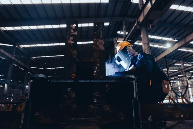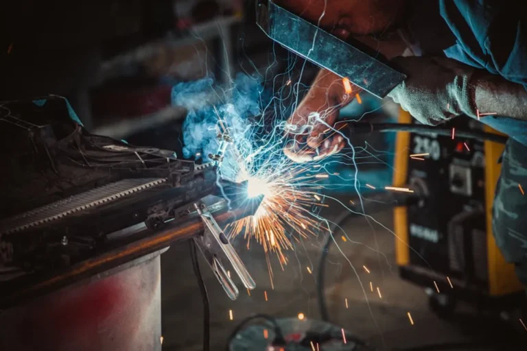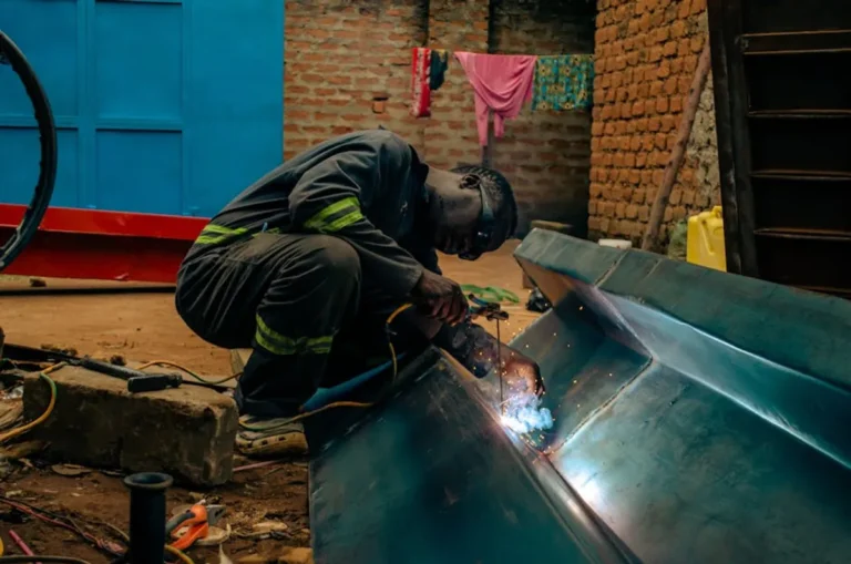
MIG welding relies on a consistent, protective gas shield to prevent atmospheric contamination, ensuring strong, clean welds. The pressure at which this shielding gas is delivered—measured as flow rate—is not a secondary consideration but a primary determinant of weld quality, efficiency, and overall project cost. Incorrect gas pressure leads to defects ranging from porosity and excessive spatter to poor penetration, demanding rework and wasting consumables. Understanding how to set and troubleshoot gas pressure effectively is fundamental for any welder seeking consistent, high-integrity results.
Understanding Shielding Gas Flow
The flow of shielding gas is controlled by two primary components: the regulator and the flowmeter. The regulator reduces the high pressure from the gas cylinder to a workable pressure for the welding process. The flowmeter, often integrated with the regulator, then precisely measures and controls the volume of gas delivered to the welding gun, typically expressed in cubic feet per hour (CFH) or liters per minute (LPM). While the regulator sets the working pressure, it's the flowmeter reading that dictates the actual gas volume reaching the weld puddle, forming the crucial protective envelope.
Optimal Gas Flow Rates for Common Shielding Gases
Establishing the correct flow rate is a balance, as too little gas fails to protect the weld, and too much can create turbulence, drawing in atmospheric contaminants, or simply waste gas. General starting points exist for common gas types:
- Argon (Ar): Often used for aluminum and stainless steel, Argon typically requires flow rates between 15-25 CFH (7-12 LPM). Its heavier density provides good coverage at lower flow rates.
- Carbon Dioxide (CO2): Preferred for mild steel, CO2 requires slightly higher flow rates, usually 20-30 CFH (9-14 LPM). It's less dense than Argon and provides a broader, more aggressive arc.
- Argon/CO2 Mixes (e.g., C25 - 75% Argon, 25% CO2): These versatile mixes, common for mild steel, generally operate effectively at 20-35 CFH (9-16 LPM). The higher end of this range is often necessary for thicker materials or higher amperage.
These figures are starting points. Fine-tuning is always necessary based on specific application parameters.
Factors Influencing Flow Settings
Several variables necessitate adjustments to the initial gas flow rate:
Material Thickness
Thicker materials often require higher amperages and longer arc times, demanding a more robust gas shield. Increasing the flow rate by 5-10 CFH above the baseline for very thick sections can help maintain adequate coverage.
Wire Diameter and Amperage
Larger wire diameters and higher amperages generate more heat and a larger weld puddle, which needs a wider and more stable gas envelope. Higher current settings generally correlate with a need for increased gas flow to prevent atmospheric intrusion.
Nozzle Size
The welding gun's nozzle size directly impacts the gas coverage area. Larger nozzles can accommodate higher flow rates more effectively without creating excessive turbulence, while smaller nozzles may require slightly reduced flow to prevent gas waste or turbulence.
Environmental Conditions
Drafts, even subtle ones from open doors or fans, can disrupt the gas shield, pulling contaminants into the weld. In such environments, increasing the gas flow rate by 5-10 CFH is often necessary to compensate for shield dissipation. However, this should be a last resort; shielding the welding area from drafts is always the preferred solution.
Pro Tip: Always check for gas leaks in your system. A small leak in the hose, regulator, or gun connections can significantly reduce the effective gas flow to the weld puddle, leading to porosity despite the flowmeter showing an adequate reading. Use a leak detection spray or soapy water on connections to identify and rectify any issues before welding.
Common Issues from Incorrect Gas Pressure
Troubleshooting weld defects often begins with verifying gas pressure and flow:
Porosity
This is the most common indicator of insufficient gas shielding. Porosity appears as small holes or voids in the weld bead, caused by atmospheric gases (oxygen, nitrogen) becoming trapped in the molten metal. If the flow rate is too low, or if drafts are present, porosity will occur. Conversely, excessive flow can also cause turbulence, drawing air into the shield and resulting in porosity.
Excessive Spatter
While often linked to voltage or wire feed speed, an unstable or inadequate gas shield can contribute to excessive spatter. Inconsistent gas flow can lead to arc instability, causing the molten metal to be expelled violently from the weld puddle.
Poor Penetration/Lack of Fusion
Though less directly tied to gas pressure, severe porosity caused by insufficient shielding can weaken the weld, making it appear to have poor penetration or lack of fusion, as the weld metal isn't solid throughout.
Unstable Arc
An arc that wavers, flickers, or is difficult to maintain can sometimes be traced back to an inconsistent or insufficient gas shield. Without a stable protective atmosphere, the arc struggles to ionize the gas efficiently, leading to poor arc performance.
Practical Setup and Adjustment Steps
- Verify Connections: Ensure all gas connections—cylinder to regulator, regulator to machine, machine to gun—are tight and leak-free.
- Open Cylinder Valve: Slowly open the main gas cylinder valve fully.
- Set Regulator Pressure: Adjust the regulator to the manufacturer's recommended delivery pressure, if applicable, or a general working pressure if only a flowmeter is present.
- Purge Line: Briefly press the gun trigger (without welding) to purge air from the gas line and allow the flowmeter to stabilize.
- Adjust Flowmeter: While purging, set the flowmeter to your chosen starting CFH/LPM, observing the ball float or digital display.
- Test Weld and Observe: Make a test weld on scrap material and visually inspect for signs of porosity or other defects. Adjust flow rate incrementally (2-5 CFH) if issues arise.
Ensuring Weld Quality and Efficiency
Mastering MIG welding gas pressure settings is an ongoing process of observation and adjustment. It directly impacts the structural integrity and aesthetic finish of your welds, while also influencing consumable usage and overall project timelines. By understanding the function of your regulator and flowmeter, adhering to recommended starting points, and actively troubleshooting common issues, welders can significantly reduce defects, minimize rework, and achieve more consistent, high-quality results. Regular checks for leaks and environmental factors will help maintain optimal gas shielding, ensuring that every weld benefits from a clean, stable arc.
Frequently Asked Questions
What happens if MIG welding gas pressure is too high?
Excessive gas flow can create turbulence around the weld puddle, drawing in ambient air and leading to porosity. It also wastes shielding gas, increasing operating costs unnecessarily.
How do I know if my gas flow is correct?
The primary indicator is the quality of the weld. Look for a clean, smooth bead free of porosity or excessive spatter. An audible hiss from the nozzle when the trigger is pulled is normal, but a strong blast indicates excessive flow. A visual inspection of test welds on scrap material is the most reliable method.
Can I use different gas flow rates for different welding positions?
Yes, welding in out-of-position scenarios (vertical, overhead) may sometimes require a slightly higher gas flow rate to ensure the shielding gas adequately covers the weld puddle against gravity and convection currents. However, this adjustment should be minimal to avoid turbulence.
How often should I check my gas flow rate?
It's good practice to check your gas flow rate before starting any significant welding project or at the beginning of each welding session. Regularly inspect hoses and connections for leaks, and periodically verify the flowmeter's calibration against a known standard if precision is critical.